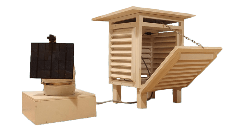
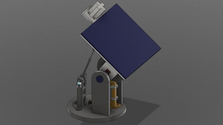
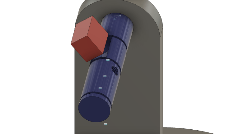
The Solar Tracker consists of two main parts: a meteorologic cage and a solar panel positioning system attached to a box containing all the electronics and controllers.
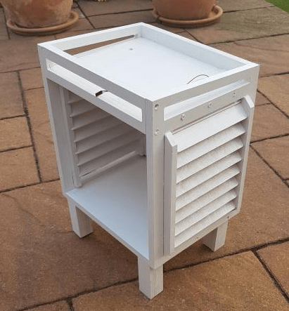
The meteorologic cage has specially inclined slats that allow air circulation but keep water from getting inside. This function is very important because the weather and air quality sensors inside can’t get wet.
In the second box, I located the “brain” of my device: an arduino microcontroller, prototyping boards with electric circuits, batteries and the entire mechanical system. I used two servo motors to rotate the special shafts that keep the solar panel set to an appropriate angle to the sun. I used one ball bearing and one cone bearing to minimize the friction while moving the platform.
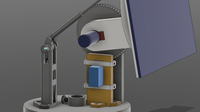
The idea that I’m most proud of is the special counter force system. I used a spring and towers connected to both the solar panel and the plate. This spring has unique properties and works as a counterforce to the force of gravity affecting the moving panel. As the solar panel lowers and the gravity force increases, the spring expands and its counterforce grows. Therefore, there is no need for any breaks or special motors to hold the solar panel in its position.
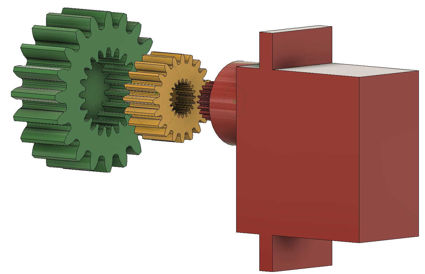
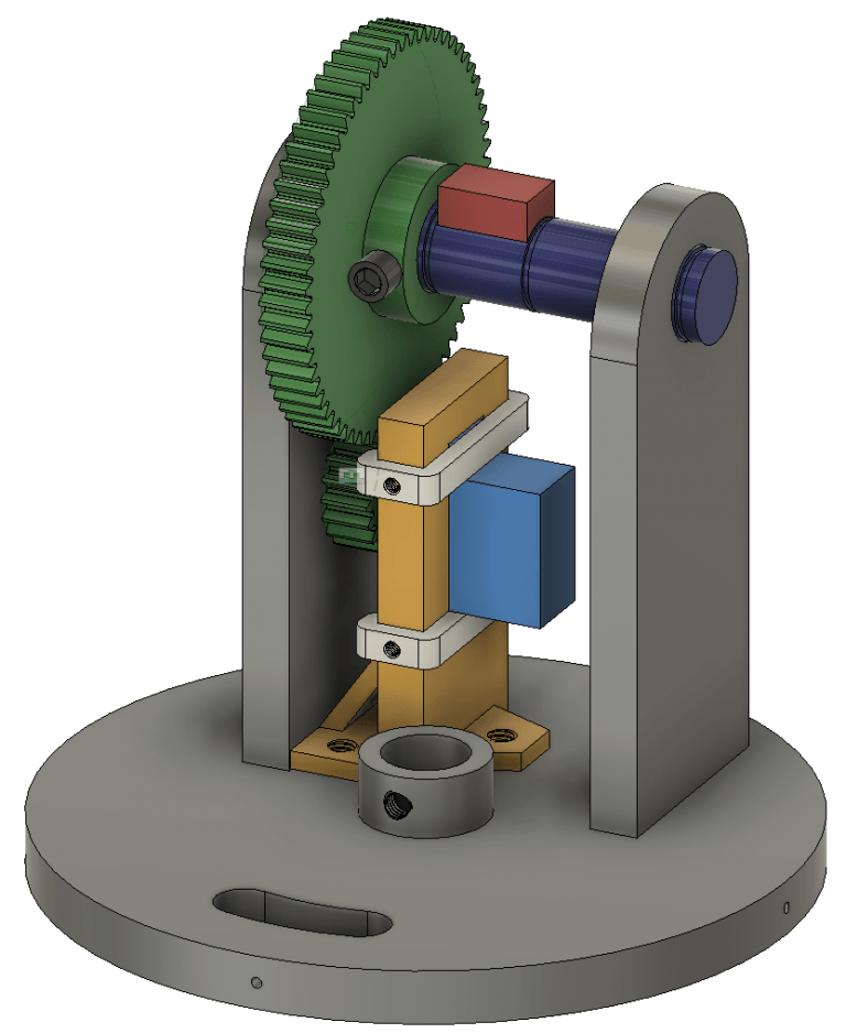
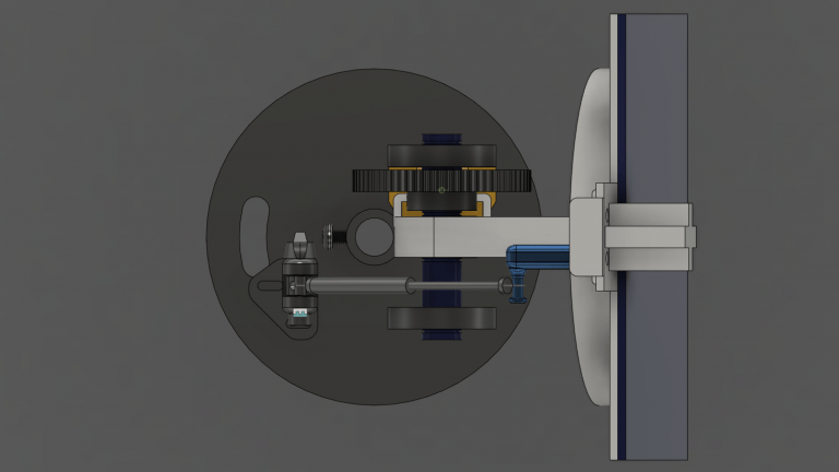
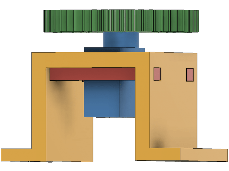
The solar panel is moved upside-down by a servo motor through gears that rotate a special shaft.
The main gear (green) is connected to the motor shaft via the second gear (orange). I decided to do so because the only way to connect the gear to the motor shaft is by gluing them together. I couldn’t glue the main gear to the shaft, because I had to be able to take off this gear in order to disconnect the motor from the shaft and the whole system.
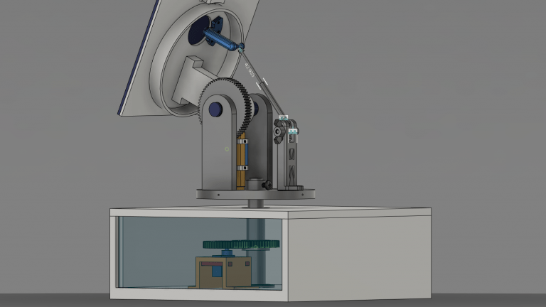
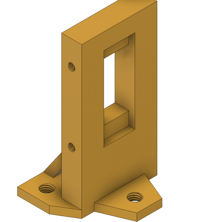
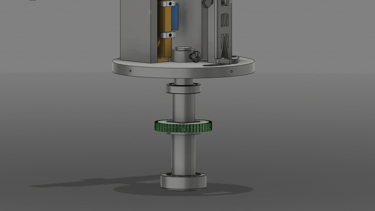
The solar panel is moved horizontally by a servo motor through gears that rotate a special shaft located in a cone bearing.
The cone bearing is located in the floor of the main box, and the ball bearing is located in the upper plywood board. Doing so the shaft stays straight and still and the friction is minimal.
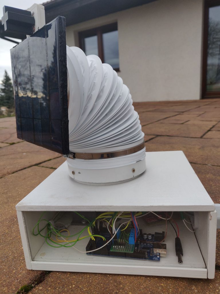
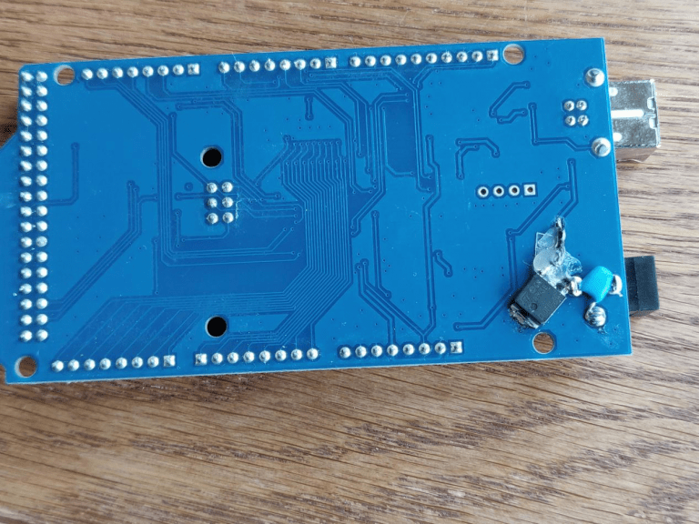
In order to reduce power losses I remade an arduino mega. Therefore my device could work significantly longer than with a factory new microcontroller.
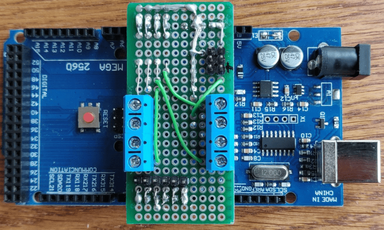
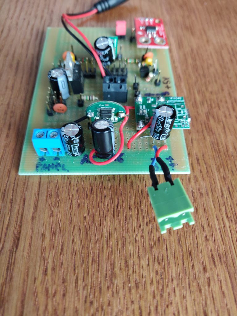
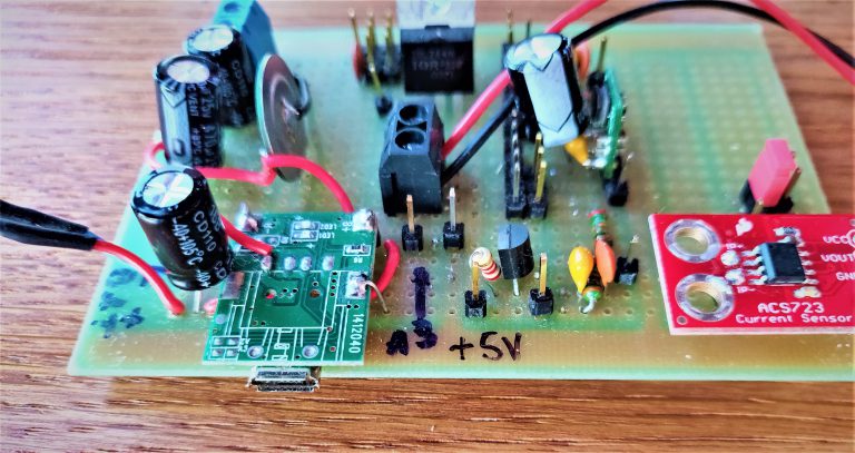
I also fabricated a special double-layer circuit board for my arduino to reduce the numbers of cables in the device and also extend its possibilities.
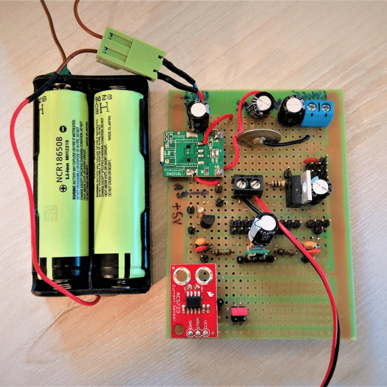
The main electric circuit distributes energy from the solar panel to the microcontroller, servo motors, sensors and batteries. Its secondary function is to monitor battery charging and discharging process.
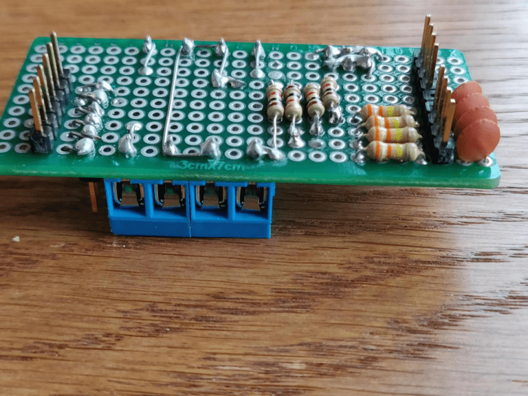
I soldered all the prototyping boards and electronic components and drew the electronic circuits on my own.